SA Sand Seperator
- Classification:product display
- source:Jiujiang FEIDA Machinery CO. Ltd
- release time:2023-04-22 17:33:39
- Views:808
SA Sand Seperator
- Classification:product display
- source:Jiujiang FEIDA Machinery CO. Ltd
- release time:2023-04-22 17:33:39
- Views:808
SA spiral sand (slag) and water separator
一、Usage and instruction :
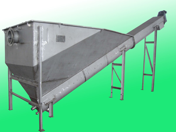
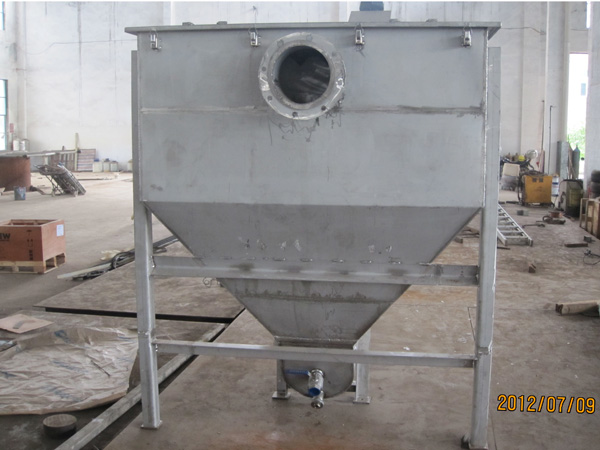
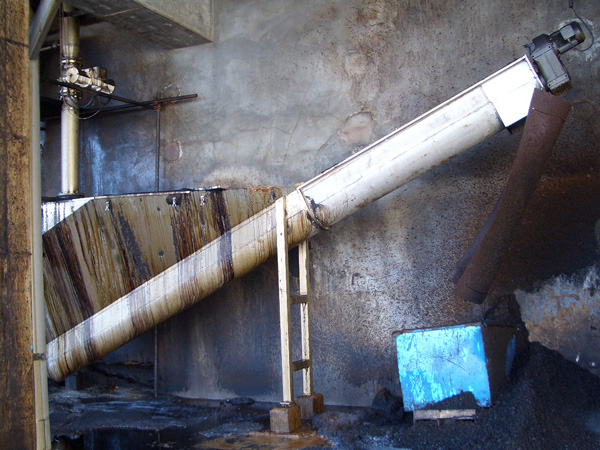
SA spiral sand (slag) and water separator is developed according to our foreign merchants' requirements. It's a solid-liquid separation equipment, it's a a shaftless screw conveyor, the blade is not easy winding and sticking sludge.It's mainly used in sewage treatment plants,paper mills,chemical plants, steel mills, power plants, aluminum plants, soda ash plant industry.

二、Structure and principle of operation::
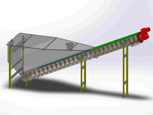
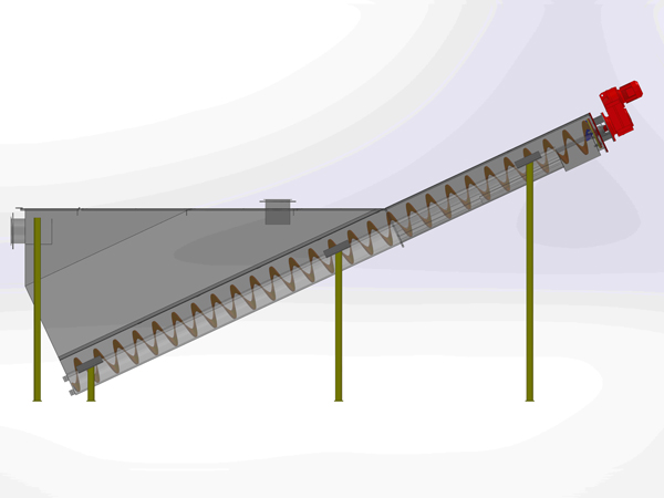
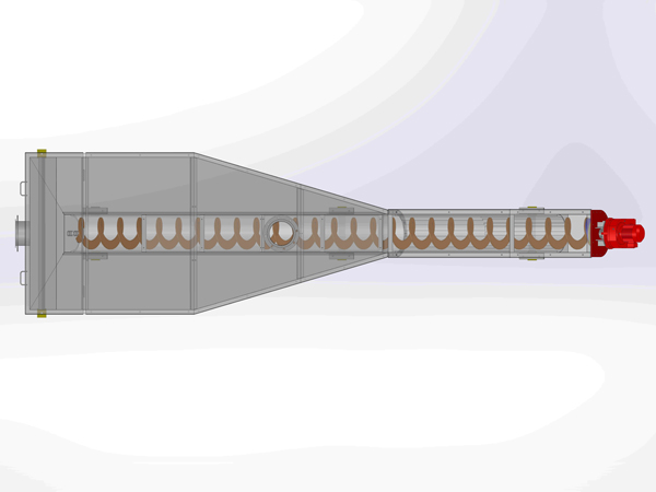
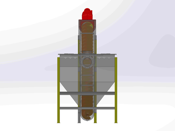
1.reducer 2.inlet 3.sedimentation tank 4.lid 5.overflow port 6.pollution discharge tap
7.the sand conveying pipe U groove 8.shaftless helical blade 9.bearing support 10.sand (slag) outlet
Procedure:Sand (slag) water mixture from the sand (slag) water inlet 2 into the sedimentation tank 3, the proportion of mixture of large sand (slag) particle under gravity will drop deposition in the water storage tank (tank) at the bottom of the sand conveying pipe of U type groove 7, by a motor speed reducer 1 driven to rotate slowly. Sand (slag) shaftless helical blade 8 slow rotation, continuous sand (slag) along the sand conveying inclined (slag) tube U slot 7 propulsion, with sand (slag) the upward, away from the liquid surface after the realization of sand (slag) separation and water, continue over a distance (the water filter), fully dried sand (slag) diameter sand row U groove on the (slag) export 10 exclusion, finally realizes the sand (slag) water separation; sand (slag) after the separation the water discharged from the overflow port 5 .
三、Main characteristic:
1、The separation efficiency can be as high as 96~98%, isolated diameter ≥ 1mm particles.
2、With shaftless spiral structure, bearing external, convenient maintenance and low cost of repair.
3、Simple structure, compact and light weight.
4、We use the wear-resistant steel to ensure the durability of the blade.The thickness can be customized. In addition to extract hard slag particles, spiral blades can be lining wear resistant materials, the service life is greatly improved. The blade can be designed to be removable, convenient for the user to repair and replacement.
5、After the separation of slag, water content is less than or equal to 30%.
6、Reducer is shaft mounted, without coupling,convenient to install.
7、The separator contains the storage tank and U shaped groove.The inlet flange is set on the upper part of the tank to receive the sinking sand (slag) from mixed liquid pool.A water distribution plate is set at the inlet below to reducing water impact. Set the water outlet flange behind the tank, return the overflow weir plate is discharged from the overflow port. Replace resistant lining board in U type groove to support shaftless leptospira. Shaftless screw is drive to rotary motion by a motor and a speed reducer.
8、The hinge cover is set on the top of the separator ,is easy to inspect the overflow and emissions.
9、Sand (slag) spiraldevice in the form of a shaftless screw, the structure design is to ensure smooth the material without blocking and winding.
10、Sand (slag) bearing water separator has a reliable sealing, have strong wear resistance and good self-lubricating performance.
11、The driving device is placed at the top which can direct drive shaft without coupling.
12、The driving device has overload protection, can satisfy 24 hours of continuous operation.
四、Structure diagram of product improvement:
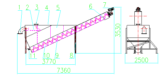
1. overflow port 2.flow plate 3.inlet 4.lid 5.sedimentation tank 6.outlet
7.reducer 8.bearing support 9.shaftless helical blade 10.the sand conveying pipe U groove 11.pollution discharge tap
Procedure:Sand (slag) water mixture from the sand (slag) water inlet 3 by flow plate 2 into the front of sedimentation tank5, in the mixture of large sand (slag) particle under gravity will drop deposition in the water storage tank (tank) at the bottom of the sand conveying pipe of U type groove 10, by a motor speed reducer 7 drive slowly rotating the sand (slag) shaftless helical blade 9 slow rotation,continuous sand (slag) along the sand conveying inclined (slag) tube U slot 10 propulsion, with sand (slag) the upward, away from the liquid surface after the realization of sand (slag) separation and water, to lapse after a certain distance (water), fully dried sand (slag) diameter sand row U groove discharged from the (slag) outlet 6 which finally realizes the sand (slag) water separation; and sand (slag) after the separation the water will discharged from the overflow port 1.
五、Comparison:
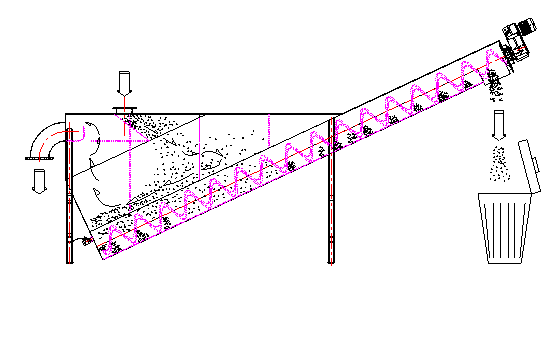
Structure diagram before improvement:
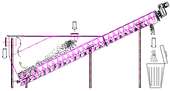
Structure diagram after improvement:
Before improvement:
1.Water inlet is near the overflow outlet which is bad for separate the sand (slag)from water.
2.Sand (slag) flow through a steady flow plate into the front of sedimentation tank ,the proportion of mixture of large sand (slag) particle under gravity will drop into the deposition storage tank (tank) at the bottom of the sand conveying pipe of U type groove, but the impact of material flow to the upper end of the spiral will turn sedimentation tank.The upper part of the material separated from material, is not conducive to the sedimentation, water storage tank at the bottom of the bottom sediment diluted, greatly effects the spiral blade trapping volume, which greatly weakened the work efficiency.
After improvement:
1.Water inlet is far from overflow outlet which can easily separate the sand (slag)from water.
2.The proportion of mixture of large sand (slag) particle slide along the sand conveying pipe U groove under gravity force, and deposition in the water storage tank.While promote the sand(slag)which is less susceptible to flow effect, so it will improved the work efficiency.
六、Performance Parameter:
Performance Parameter
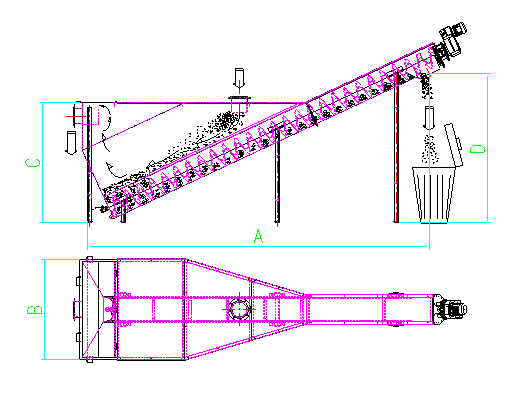
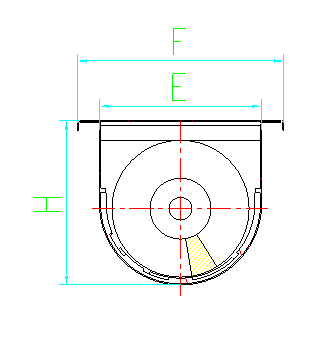
Performance Parameter
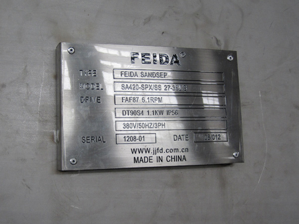
Model SA | U250 | U320 | U355 | U420 |
spiral diameter O mm | 215 | 280 | 315 | 365 |
U groove diameter mm | 250 | 320 | 355 | 420 |
U groove width mm | 354 | 424 | 459 | 545 |
U groove height H mm | 260 | 329 | 364 | 421 |
speed RPM | 25 | 25 | 25 | 25 |
delivery value m3/h | 20-50 | 50-75 | 75-100 | 100-125 |
flight cross section | 70*8 | 80*10 | 80*10 | 100*15 |
superficial area m2 | 2.3 | 3 | 4 | 5 |
volume m3 | 1.2 | 1.8 | 3.3 | 4.2 |
horizontal project A mm | 3850 | 4400 | 5900 | 6300 |
width B mm | 1250 | 1500 | 1500 | 1800 |
height C mm | 1500 | 1700 | 2150 | 2150 |
elevate height D mm | 1500 | 1700 | 2350 | 2600 |
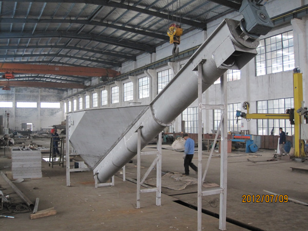
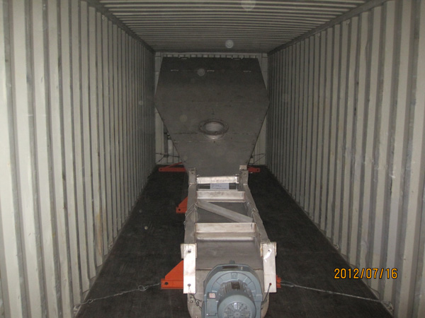
success cases
Scan the QR code and read it with your mobile phone
Jiujiang FEIDA Machinery CO. Ltd
Service Hotline:
company address:
No.16 Shun Xing Road, Ecological Industrial Park, Lushan District, Jiujiang,Jiangxi.P.R. China
Jiujiang FEIDA Machinery CO. Ltd
all rights reserved:Jiujiang FEIDA Machinery CO. Ltd

